BIOS Setup
Introduction
The system has AMI BIOS built-in, with a SETUP utility that allows users to configure required settings or to ativate certain system features. Pressing Tab or Del key immediately allows you to enter the Setup Utility.
Enter BIOS Setup
To enter the BIOS setup utility, simply follow the steps below:
Boot up the system
Press Del during the boot-up if you connect a keyboard to this unit. But if you connect a PC to this unit through console USB/Serial connection, then press Tab. Your system should be running POST (Power-On-Self-Test) upon booting up.
Then you will be directed to the BIOS main screen.
Instructions of BIOS navigations.
Control Keys |
Description |
|---|---|
→← |
select a setup screen, for example, [Main],[Advanced] and [Platform] |
↑↓ |
select an item/option on a setup screen |
Enter |
select an item/option or enter a sub-menu |
+/- |
to adjust values for the selected setup item/option |
F1 |
to display General Help screen |
F2 |
to retrieve previous values |
F3 |
to load optimized default values |
F4 |
to save configurations and exit BIOS |
Esc |
exit the current screen |
Main Page
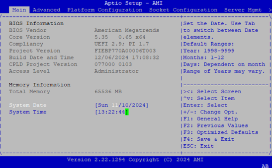
Setup Main Page contains BIOS information and project version information.
Item |
Description |
|---|---|
BIOS Information |
BIOS Vendor: American Megatrends |
Memory Information |
Total Memory: by case |
System Date |
To set the Date, use Tab to switch between Date elements. |
System Time |
To set the Date, use Tab to switch between Date elements. |
Advanced Page
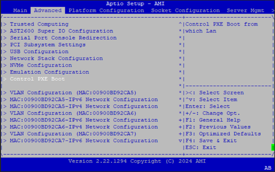
Select the Advanced menu tab from the BIOS setup screen to enter the “Advanced” setup screen. Users can slect any of the items in the left frame of the screen
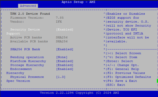
Trusted Computing
Feature |
Options |
Description |
|---|---|---|
Security Device Support |
Enabled |
Enables or Disables BIOS support for security device. O.S. will not show Security Device. TCG EFI protocol and INT1A interface will not be available. |
SHA256 PCR Bank |
Enabled |
Enable or Disable SHA256 PCR Bank |
Pending operation |
None |
Schedule an Operation for the Security Device. |
Platform Hierarchy |
Enabled |
Enable or Disable Platform Hierarchy |
Storage Hierarchy |
Enabled |
Enable or Disable Storage Hierarchy |
Endorsement Hierarchy |
Enabled |
Enable or Disable Endorsement Hierarchy |
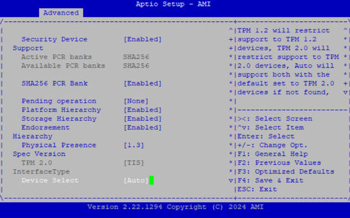
Physical Presence Spec Version |
1.2 |
Select to Tell O.S. to support PPI Spec Version 1.2 or 1.3. |
TPM 2.0 InterfaceType |
TIS |
Select the Communication Interface to TPM 2.0 Device |
Device Select |
TPM 1.2 |
TPM 1.2 will restrict support to TPM 1.2 devices, TPM 2.0 will restrict support to TPM 2.0 devices, Auto will support both with the default set to TPM 2.0 devices if not found, TPM 1.2 devices will be enumerated |
Super IO Configuration
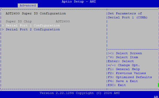
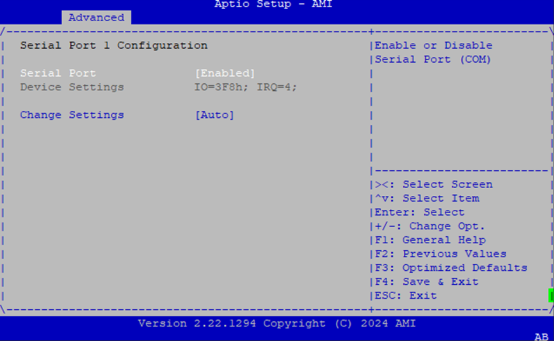
Serial Port 1 Configuration
Feature |
Options |
Description |
|---|---|---|
Serial Port |
Enabled |
Enable or Disable Serial Port (COM) |
Device Settings |
IO=3F8h; IRQ = 4 |
N/A |
Change Settings |
Auto |
Select an optimal setting for Super IO Device |
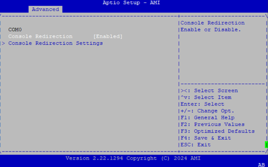
Serial Port Console Redirection
Feature |
Options |
Description |
|---|---|---|
Console Redirection |
Enabled |
Console Redirection Enable or Disable |
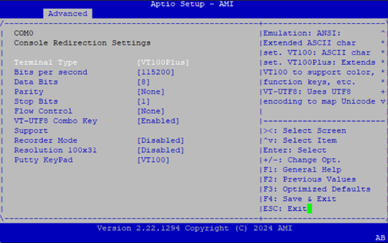
Console Redirection Settings
Feature |
Options |
Description |
|---|---|---|
Terminal Type |
VT100 |
Emulation: |
Bits per Second |
9600 |
Selects serial port transmission speed. The speed must be matched on the other side. Long or noisy lines may require lower speeds. |
Data Bits |
7 |
Data Bits |
Parity |
None |
A parity bit can be sent with the data bits to detect some transmission errors. Even: parity bit is 0 if the num of 1’s in the data bits is even. Odd: parity bit is 0 if num of 1’s in the data bits is odd. Mark: parity bit is always 1. Space: Parity bit is always 0. Mark and Space Parity do not allow for error detection. They can be used as an additional data bit. |
Stop Bits |
1 |
Stop bits indicate the end of a serial data packet. (A start bit indicates the beginning). The standard setting is 1 stop bit. Communication with slow devices may require more than 1 stop bit. |
Flow Control |
None |
Flow control can prevent data loss from buffer overflow. When sending data, if the receiving buffers are full, a ‘stop’ signal can be sent to stop the data flow. Once the buffers are empty, a ‘start’ signal can be sent to re-start the flow. Hardware flow control uses two wires to send start/stop signals. |
VT-UTF8 Combo Key Support |
Disabled |
Enable VT-UTF8 Combination Key Support for ANSI/VT100 terminals. |
Recorder Mode |
Disabled |
With this mode enabled only text will be sent. This is to capture Terminal data. |
Resolution 100x31 |
Disabled |
Enables or disables extended terminal resolution |
Putty Keypad |
VT100 |
Selects Function Key and Keypad on Putty. |
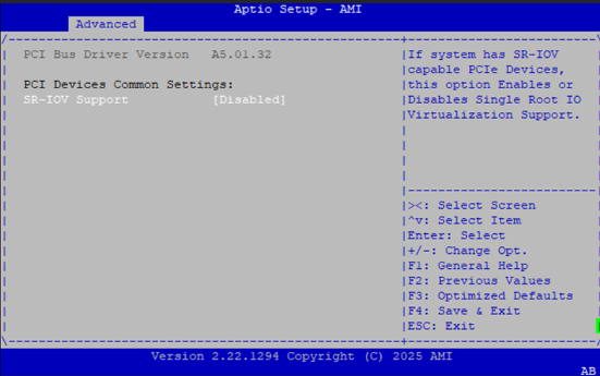
PCI Subsystem Settings
Feature |
Options |
Description |
|---|---|---|
SR-IOV Support |
Disabled |
If system has SR-IOV capable PCIe Devices, this option Enables or Disables Single Root IO Virtualization Support. |
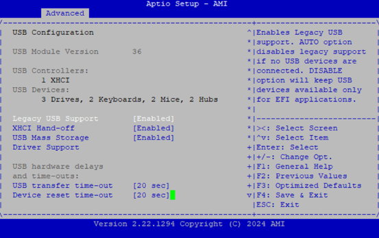
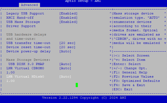
USB Configuration
Feature |
Options |
Description |
|---|---|---|
Legacy USB Support |
Enabled |
|
XHCI Hand-off |
Enabled |
|
USB Mass Storage |
Enabled |
|
Driver Support |
Disabled |
|
USB transfer time-out |
1 sec |
|
Device power-up delay |
Auto |
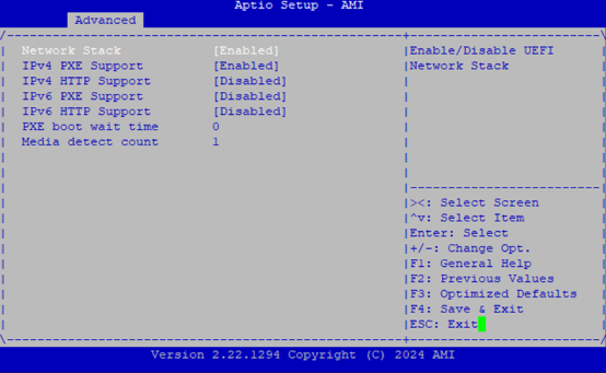
Network Stack Configuration
Feature |
Options |
Description |
|---|---|---|
Network Stack |
Disabled |
Enables or disables UEFI Network Stack |
IPv4 PXE Support |
Disabled |
Enable/Disable IPv4 PXE boot support. If disabled, IPv4 PXE boot support will not be available. |
IPv4 HTTP Support |
Disabled |
Enable/Disable IPv4 HTTP boot support. If disabled, IPv4 HTTP boot support will not be available. |
IPv6 PXE Support |
Disabled |
Enable/Disable IPv6 PXE boot support. If disabled, IPv6 PXE boot support will not be available. |
IPv6 HTTP Support |
Disabled |
Enable/Disable IPv6 HTTP boot support. If disabled, IPv6 HTTP boot support will not be available. |
PXE boot wait time |
0 |
Wait time in seconds to press ESC key to abort the PXE boot. Use either +/- or numeric keys to set the value. |
Media detect count |
1 |
Number of times the presence of media will be checked. Use either +/- or numeric keys to set the value. |
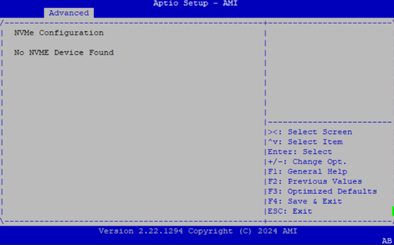
NVMe Configuration
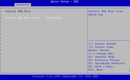
Control PXE Boot
Feature |
Options |
Description |
|---|---|---|
Control PXE Boot from |
Disabled |
Control PXE Boot from which Lan. |
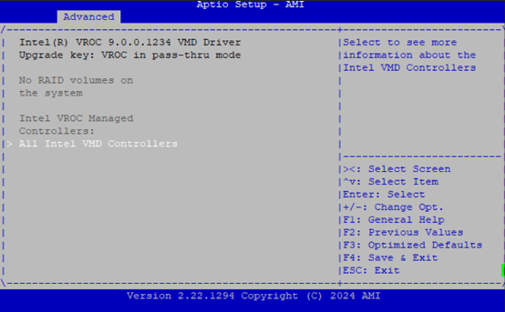
Intel VROC
Platform Configuration
Select the Platform menu item from the BIOS setup screen to enter the Platform Setup screen. Users can select any of the items in the left frame of the screen.
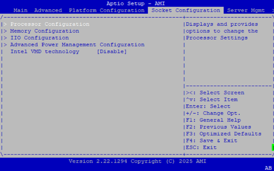
Socket Configuration
Select the Socket menu item from the BIOS setup screen to enter the Socket Setup screen. Users can select any of the items in the left frame of the screen.
Feature |
Options |
Description |
|---|---|---|
Processor Configuration |
None |
Displays and provides option to change the Processor Settings |
Memory Configuration |
None |
Displays and provides option to change the Memory Settings |
IIO Configuration |
None |
Displays and provides option to change the IIO Settings |
Advanced Power Management Configuration |
None |
Displays and provides option to change the Power Management Settings |
Intel VMD technology |
Disable Enable |
Enable/Disable VMD this IIO Domain. |
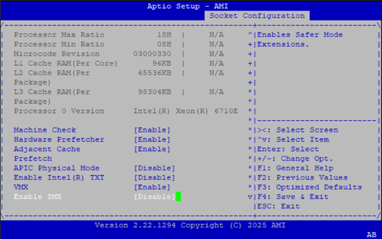
Processor Configuration
Feature |
Options |
Description |
|---|---|---|
Machine Check |
Disabled |
Enable or Disable the Machine Check |
Hardware Prefetcher |
Disabled |
MLC Streamer Prefetcher (MSR 1A4h Bit [0]) |
Adjacent Cache Prefetcher |
Disabled |
MLC Spatial Prefetcher (MSR 1A4h Bit [1]) |
APIC Physical Mode |
Disabled |
Enable/Disable the APIC physical destination mode |
Enable Intel® TXT |
Disabled |
Enables Intel(R) TXT |
VMX |
Disabled |
Enables the Vanderpool Technology, which takes effect after reboot. |
Enable SMX |
Disabled |
Enables Safer Mode Extensions |
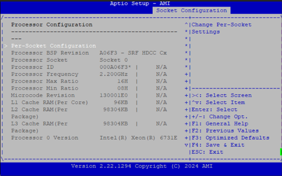
Per-Socket Configuration
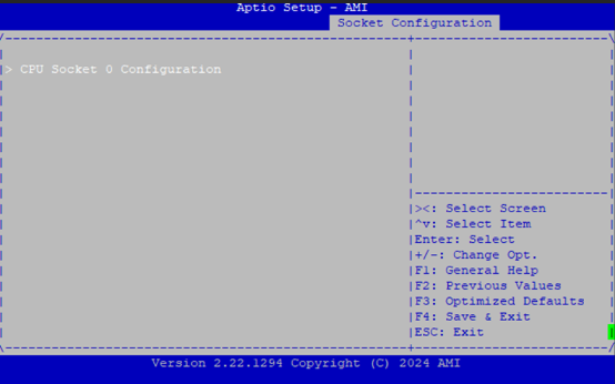
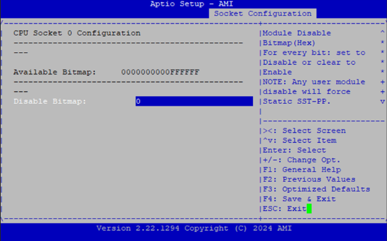
CPU Socket0 Configuration
Feature |
Options |
Description |
|---|---|---|
Disable Bitmap (Hex) |
0 |
0: Enable all cores. FFFFFFFFFFF: Disable all cores least one core per CPU must be enabled. Disabling all cores is an invalid configuration. |
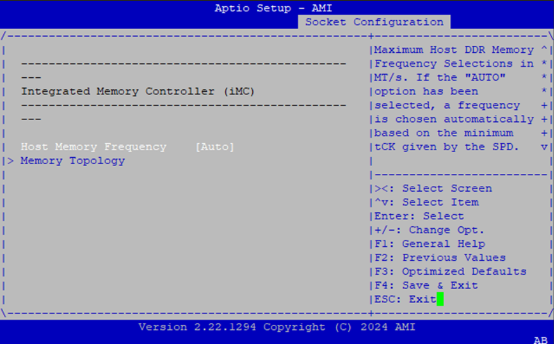
Memory Configuration
Feature |
Options |
Description |
|---|---|---|
Host Memory Frequency |
Auto |
Maximum Memory Frequency Selections in MT/s. If the “AUTO” option has been selected, a frequency is chosen automatically based on the minimum tCK given by the SPD. If Enforce POR is disabled, user will be able to run at higher frequencies than the memory support (limited by processor support) |
Memory Topology |
None |
Displays memory topology with Dimm population information |
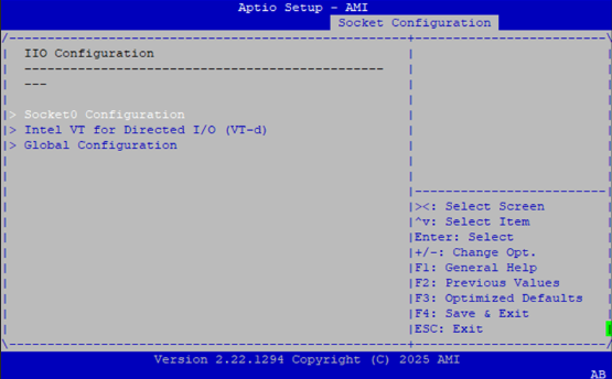
IIO Configuration
Feature |
Options |
Description |
|---|---|---|
Socket0 Configuration |
None |
PCI Express Root Port setting page |
Intel VT for Directed I/O (VT-d) |
None |
Intel VT-d technology setting page. |
Global Configuration |
None |
For all PCI Express Root Port setting page |
Socket0 Configuration
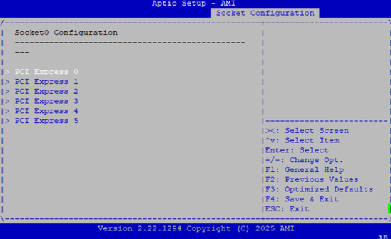
Feature |
Options |
Description |
|---|---|---|
PCI Express 0~8 |
None |
PCI Express 0~8 can adjust root port setting, such as bifurcation, VMD…etc. |
PCI Express 0
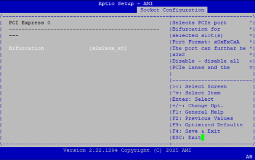
Feature |
Options |
Description |
|---|---|---|
Bifurcation |
Auto |
Selects PCIe port Bifurcation for selected slot(s): |
Global Configuration
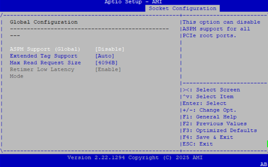
Feature |
Options |
Description |
|---|---|---|
ASPM Support (Global) |
Disable |
This option can disable ASPM support for all PCIe root ports. |
Extended Tag Support |
Disable |
This option can disable 8-bit Tag support in all PCIe root ports. ‘Auto’ keeps hardware default. |
Max Read Request Size |
Auto |
Set Max Read Request Size in End Points |
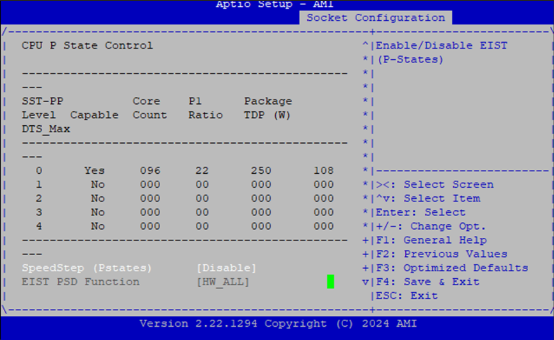
Advanced Power Management Configuration
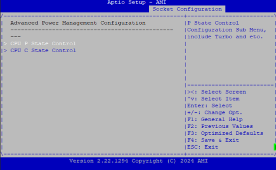
CPU P State Control
Feature |
Options |
Description |
|---|---|---|
SpeedStep (Pstates) |
Disable |
Enables or disables EIST (P-States). |
EIST PSD Function |
HW_ALL |
Choose HW_ALL/SW_ALL in _PSD return. |
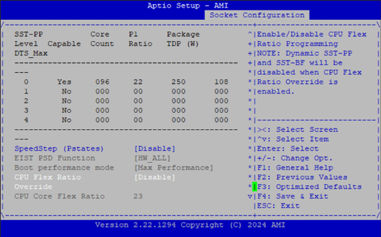
Boot performance mode |
Max Performance |
Select the performance state that the BIOS will set before OS hand off. |
Turbo Mode |
Disable |
Enable/Disable processor Turbo Mode. |
Energy Efficient Turbo |
Enable |
Enable/Disable Energy Efficient Turbo. |
CPU Flex Ratio |
Disabled |
Enable/Disable CPU Flex Ratio Programming. |
Override |
Enabled |
Note: Dynamic SST-PP and SST-BF will be disabled when CPU Flex Ratio Override is enabled. |
CPU Core Flex Ratio |
23 |
Non-Turbo Mode Processor Core Ratio Multiplier. |
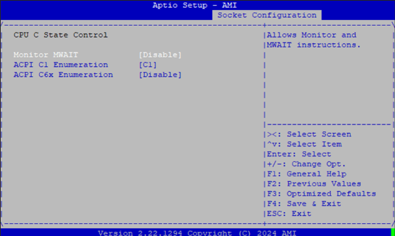
CPU C State Control
Feature |
Options |
Description |
|---|---|---|
Monitor MWAIT |
Disable |
Allows Monitor and MWAIT instructions. |
ACPI C1 Enumeration |
C1 |
Enumerate C1/C1e as ACPI C1. |
ACPI C6x Enumeration |
Disable |
AUTO: Maps to C6S-P as ACPI C2 |
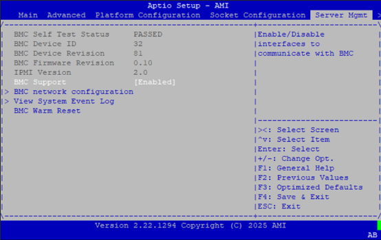
Server Mgmt
Feature |
Options |
Description |
|---|---|---|
BMC Support |
Enable |
Enable or disables interfaces to communicate with BMC. |
BMC network configuration |
NA |
Configure BMC network parameters. |
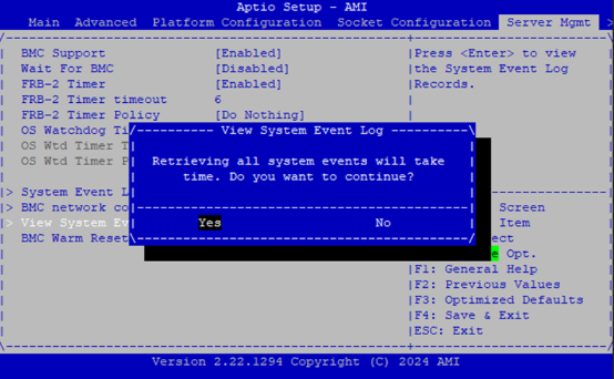
View System Event Log |
NA |
Press |
BMC Warm Reset |
NA |
Press |
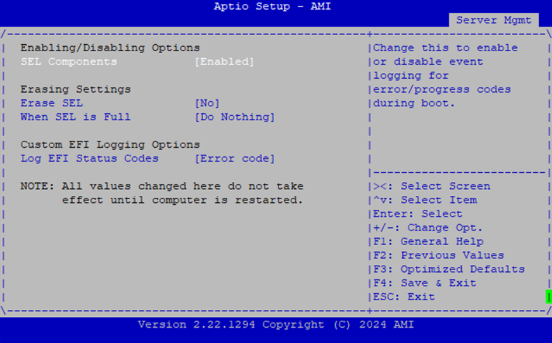
System Event Log
Feature |
Options |
Description |
|---|---|---|
SEL Components |
Enable |
Change this to enable or disable event logging for error/progress codes during boot. |
Erase SEL |
NO |
Choose options for erasing SEL. |
When SEL is Full |
Do Nothing |
Choose options for reactions to a full SEL. |
Log EFI Status Codes |
Disabled |
Disable the logging of EFI Status Codes or log only error code or only progress code or both. |
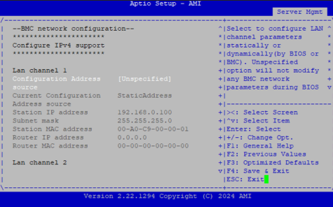
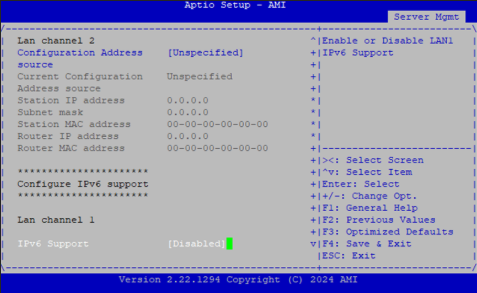
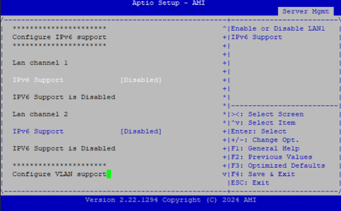
BMC Network Configuration
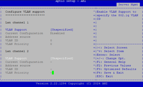
Feature |
Options |
Description |
|---|---|---|
Configuration Address source |
Unspecified |
Select to configure LAN channel parameters statically or dynamically (by BIOS or BMC). The unspecified option will not modify any BMC network parameters during BIOS phase. |
View System Event Log
Security
Select the Security menu item from the BIOS setup screen to enter the Security Setup screen. Users can select any of the items in the left frame of the screen.
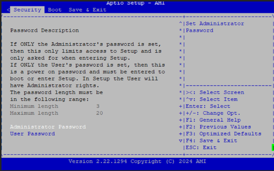
Feature |
Description |
|---|---|
Administrator Password |
If ONLY the Administrator’s password is set, it only limits access to Setup and is only asked for when entering Setup. |
User Password |
If ONLY the User’s password is set, it serves as a power-on password and must be entered to boot or enter Setup. In Setup, the User will have Administrator rights. |
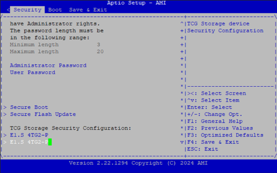
Secure Boot
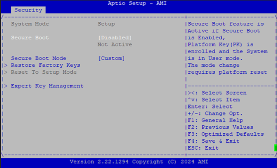
Feature |
Options |
Description |
|---|---|---|
Secure Boot |
Disable |
Secure Boot feature is Active if Secure Boot is Enabled, Platform Key(PK) is enrolled and the System is in User mode. The mode change requires platform reset. |
Secure Boot Mode |
Standard |
Key Management
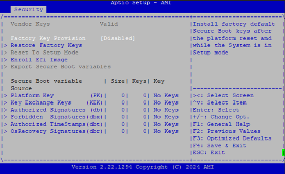
Feature |
Options |
Description |
|---|---|---|
Factory Key Provision |
Disable |
Install factory default Secure Boot keys after the platform reset and while the System is in Setup mode. |
Restore Factory keys |
None |
Force System to User Mode. Install factory default Secure Boot key databases. |
Enroll Efi Image |
None |
Allow Efi image to run in Secure Boot mode. Enroll SHA256 Hash certificate of a PE image into Authorized Signature Database (db). |
Boot Menu
Select the Boot menu item from the BIOS setup screen to enter the Boot Setup screen. Users can select any of the items in the left frame of the screen.
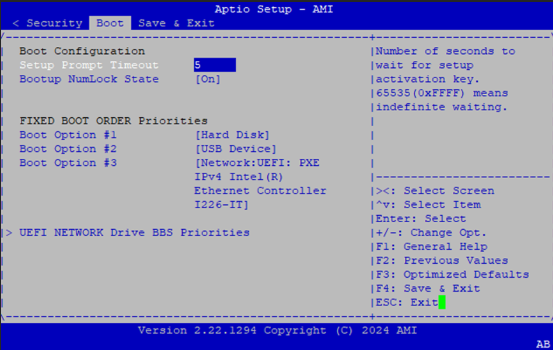
Feature |
Options |
Description |
|---|---|---|
Setup Prompt Timeout |
5 |
Number of seconds to wait for setup activation key. 65535(0xFFFF) means indefinite waiting. |
Bootup NumLock State |
On |
Select the keyboard NumLock state |
Choose boot priority from boot option group.
Choose specific boot device priority sequence from available Group device.
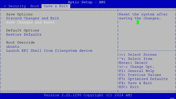
Save and Exit Menu
Select the Save and Exit menu item from the BIOS setup screen to enter the Save and Exit Setup screen. Users can select any of the items in the left frame of the screen.
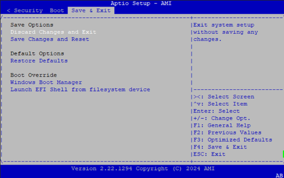
Discard Changes and Exit
Select this option to quit Setup without saving any modifications to the system configuration. The following window will appear after the “Discard Changes and Exit” option is selected. Select “Yes” to discard changes and Exit Setup.

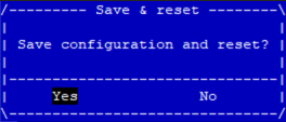
Save Changes and Reset
When Users have completed the system configuration changes, select this option to save the changes and reset from BIOS Setup in order for the new system configuration parameters to take effect. The following window will appear after selecting the “Save Changes and Reset” option is selected. Select “Yes” to Save Changes and reset.
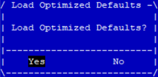
Restore Defaults
Restore default values for all setup options. Select “Yes” to load Optimized defaults.
Note: The items under Boot Override may not be the same a the image above, as it should depend on the actual devices connect to the system.
Intel® RAID Key Configuration
Configuring Intel VMD and Creating a RAID Volume
Step 1: Install the VROC Key
Connect the VROC key to the motherboard’s JRAID_CON1 header.

Step 2: Boot into BIOS
Boot into BIOS à Navigate to Socket Configuration and set Intel VMD Technology to Enabled
Save & Exit: Choose Save Changes and Reset to reboot the system.
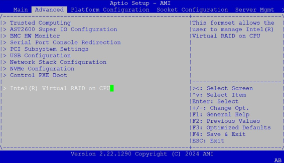
Step 3: Re-enter BIOS
After reboot, enter BIOS again.
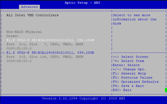
Navigate to Advanced > Intel Virtual RAID on CPU > All Intel VMD Controllers.
Select Create RAID Volume, then choose the desired RAID Level.
Select the storage devices to include in the RAID array.
Click Create Volume, then confirm with Yes.
Exit BIOS.
Step 4: Boot into the OS
Use the command lsblk to verify the RAID volume. It will appear as /dev/mdxxx